


PDF Download High Resolution
Frequently Used Terms
Surface Finish - refers to several terms, all of which can be used to describe the irregularities of a surface.
Lay - refers to the pattern direction, vertical, horizontal, radial, cross-hatched, circular, isotropic.
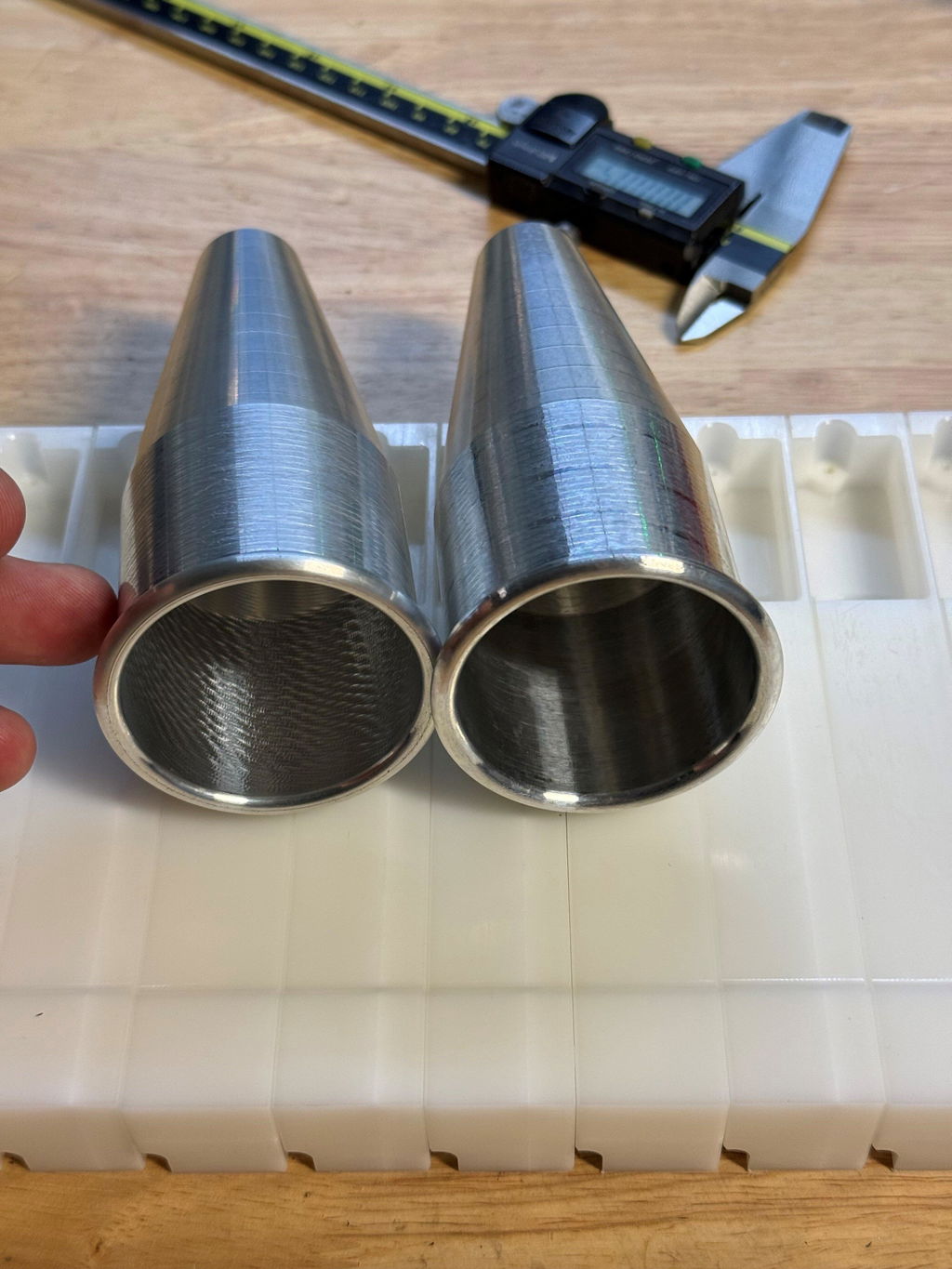
Surface Roughness - generally refers to the distance between peaks and valleys on a surface. A surface may appear smooth because it reflects light. This does not mean the finish is necessarily very smooth. If you can feel a distinct catch with your fingernail when running it on a surface, it probably isn't as low RA as it may appear from a distance.
Waviness - A great example of waviness can be if you experience chatter while machining. The resulting surface can be highly irregular even though the feed rate did not change.
Measuring Finishes - With experience one can generally see an approximate finish, however there is only one way to be certain, which is to measure. A profilometer can be used to measure the peaks and valleys of a surface. A stylus is dragged across the surface which skips along the peaks and valleys and provides a reading. There are other non-contact method of measuring as well, but they are less common in a shop environment.
Surface Finish can be a complicated topic. The chart above primarily focuses on turned and sanded finishes. Other methods of attaining a desired finish can be used, such as, grinding, bead blasting, and even chemical polishing.
A lathe turned finish is one of the easiest ways to visualize surface roughness. If you imagine a turned finish like a thread, the distance between the peaks and valleys determines the average roughness. Tool nose radius goes hand in hand with this and must be considered when turning. See the provided tool nose radius pdf. where feed rate and depth of cut are equivalent.
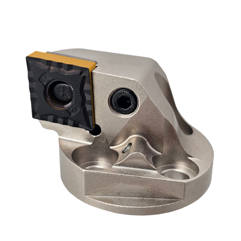
When referring to turned finishes, tool nose radius is one of the greatest determining factors in how fast you can feed and still achieve the same finish. Larger tool nose radii are more durable by a wide margin. They leave less severe peaks and valleys at an equivalent feed rate than with a smaller tool nose radius. Sounds great, right? Yes and No, larger tool nose radii create more pressure when machining, which can lead to issues with chatter. Chip control can also be a major issue as cut depths less than the tools nose radius can cause the tool to simply rub instead of cutting. They also require more horsepower to drive than a smaller insert radius. Generally, for boring operations, the smallest practical radius is chosen, which decreases the risk of chatter substantially. Feed rates must be reduced, as can be seen in the graphic, to maintain the same relative surface finish. A wiper insert, which has an edge that is situated where the straight edge meets the corner radius, can help minimize this feed rate reduction.
A straight line has zero surface roughness, so the closer an insert comes to 180° the faster you can feed. However, there are some caveats to this. A surface can be the desired roughness average, but still look poor. Steel, for instance, can appear smeared if the RPM chosen when turning is not sufficient, which can be a point of frustration. Material specific inserts can help prevent tearing or smearing when trying to achieve desirable finishes.
Using abrasives to create a desired surface finish works the same way. Imagine the abrasive as the thread, coarser abrasives will leave deeper scratches, peaks and valleys. It is usually best to work from course abrasives (lower is coarser) to finer (higher number). Skipping steps between "grits" will only lead to more time needed at each subsequent step. A common path from a rough to fine finish would be 60 grit, 80 grit, 120, grit, 180 grit, 220 grit, 320 grit, 600 grit, 1200 grit and so on until a mirror finish is attained.
A rough surface can trap more particulate than a smooth surface. Food, Medical, and Pharmaceutical applications often require finer finishes to prevent bacteria collecting in the valleys of a surface.